Choosing cutting tools for machining in 2026 means matching the tool to the work, not simply choosing the newest grade. In cutting machining, material, operation, machine rigidity, and toolholding all affect performance. A carbide insert that works well on a rigid lathe may chatter in a lighter setup. Small details matter.
Start with the workpiece. Stainless steel, aluminum, and hardened alloys place different demands on edge geometry, substrate, and coating. Then consider whether the job involves turning, milling, drilling, or finishing. Check spindle power, toolholder condition, coolant delivery, and the manufacturer’s recommended cutting data. These details help narrow the options, but they cannot guarantee a good result. Real cuts decide.
A useful selection also accounts for tool life, surface finish, cycle time, and cost per part. Record wear patterns and compare results under consistent conditions; a chipped edge may point to vibration, heat, or an unsuitable feed. Even a careful choice can miss something. Shop-floor observations are valuable, but they should be checked against reliable tooling guidance and measured results. This outline explores how to evaluate tool materials, geometries, coatings, and operating conditions, then refine the choice through controlled trials. There is no universal winner. The best tool is the one that performs reliably for your machine, material, and production needs.
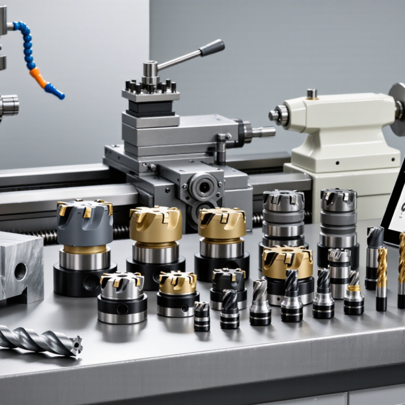
ISO 513 classifies workpiece materials into six groups: P for steel, M for stainless steel, K for cast iron, N for nonferrous metals, S for heat-resistant superalloys and titanium, and H for hardened materials. This code narrows the search for a suitable cutting tool. It does not select one by itself.
The IEA’s Energy Efficiency 2023 report estimates that industry accounted for about 37% of global final energy consumption in 2022. That figure covers all industry, not machining alone, but it makes process efficiency worth attention. Match the ISO group before comparing cutting data. A stainless-steel part, for example, may generate long, sticky chips and heat near the edge; a cast-iron part often produces shorter, abrasive chips. The tool must handle the actual material behavior.
Check hardness, alloy, surface condition, and whether the cut is interrupted. These details can shift performance within one ISO group. A small trial cut can reveal built-up edge, vibration, or rapid wear before a full run. The code is a starting point. Still, verify. ISO 513 groups materials broadly, so real shop conditions may not fit neatly into one label.
For 2026, choose the tool substrate for the workpiece and cutting load before comparing coatings. ISO 513 groups materials into categories such as steel, stainless steel, cast iron, non-ferrous metals, and heat-resistant alloys. These groups are useful starting points, not a complete recipe. Tough carbide grades can tolerate interrupted cuts and vibration, while harder grades often suit stable, continuous finishing. High-speed steel may still be practical for slower operations or complex tools. Match hardness to the cut. Too much hardness can mean a chipped edge when the setup is less rigid than expected.
Then choose a coating for heat, friction, and chip flow. PVD coatings often preserve a sharper edge, which helps with small tools and stainless steel. CVD coatings are commonly used where wear resistance and heat protection matter, such as longer cuts in steel. Check coolant use, cutting speed, and whether chips rub against the tool; a coating cannot compensate for poor chip control.
The USGS 2024 Mineral Commodity Summaries estimated 2023 global tungsten mine production at 78,000 tonnes, with 63,000 tonnes from China. That figure is a useful reminder to consider grade availability and supply continuity, not just cutting performance. There is no perfect chart. Run a controlled trial, inspect the worn edge, and adjust one variable at a time; real setups rarely behave exactly like catalog examples.
Edge geometry is not a cosmetic detail; it changes how the tool enters the material. A sharp, positive-rake edge can reduce cutting forces and heat, which helps when machining thin walls or using a less rigid setup. That matters. But a very keen edge may chip under interrupted cuts or hard inclusions. A stronger, honed edge often survives better, though it can push harder against the workpiece. Match the edge to the machine, material, and cut—not just the tool catalog.
Chip control depends on more than the breaker shape. Feed and depth of cut must fall within the geometry’s working range. A chipbreaker designed for a moderate feed may let long ribbons escape when the feed is too light. Those ribbons can scratch a finished surface or wrap around the tool. Watch the chips: short, consistent curls are usually easier to manage. Color can also signal excess heat, but it is not a complete diagnosis.
For a better finish, consider nose radius, edge preparation, and vibration together. A larger radius can improve finish, yet it also increases radial force and may cause chatter on a slender part. A small hone can strengthen the edge, but an overly heavy hone may leave a rougher surface. Test one change at a time and inspect the surface under steady lighting. The first setup may still miss the mark; record the result and adjust the geometry or cutting conditions.
| How to Choose Cutting Tools for Machining in 2026? — Select Edge Geometry to Balance Cutting Forces, Chip Control, and Finish | |||||
|---|---|---|---|---|---|
| Edge Geometry | Typical Cutting-Force Effect | Chip-Control Effect | Surface-Finish Effect | Suitable Applications | Selection Considerations |
| Positive rake, sharp edge | Generally lowers cutting forces and heat generation compared with a stronger, more negative geometry. | Promotes shearing and can help form chips in ductile materials; chip control still depends on the chipbreaker and cutting conditions. | Can produce a clean finish when the edge is sharp and stable; built-up edge may worsen finish in sticky materials. | Aluminum and other non-ferrous alloys, plastics, thin-walled parts, and setups with limited machine or workpiece rigidity. | The sharper wedge is less resistant to chipping. Use adequate edge support and avoid severe interrupted cuts unless the tool is designed for them. |
| Neutral or mildly positive rake | Usually offers a middle ground between low force and edge strength. | Can provide predictable chip formation across a moderate range of feeds and depths when paired with an appropriate chipbreaker. | Versatile; finish depends strongly on nose radius, feed, tool condition, and workpiece stability. | General-purpose turning and milling where material, cut conditions, or setup vary. | Check the toolmaker’s recommended feed and depth-of-cut range for the specific chipbreaker; one geometry will not control chips equally well at every load. |
| Negative rake or reinforced wedge | Typically requires higher cutting forces and machine power, while providing a stronger cutting edge. | Often works well in heavier cuts when the chipbreaker is matched to the feed and depth of cut. | Can maintain a consistent finish in stable, sufficiently rigid setups; vibration from excessive force can degrade finish. | Rigid machines, heavier cuts, interrupted operations, and applications requiring a robust edge. | Confirm that the workholding, spindle, and machine can handle the increased load. It may be unsuitable for slender or low-rigidity parts. |
| Small nose radius | Can reduce radial loading and deflection in some turning setups, especially on slender workpieces. | Has limited influence on chip control by itself; pair it with a chipbreaker suited to the operation. | At the same feed, generally produces a rougher theoretical turning finish than a larger radius, but may avoid chatter on flexible parts. | Finishing slender shafts, small features, and operations where radial force or clearance is a concern. | Use a suitable feed and avoid excessive load; a small radius has less edge support and can be more vulnerable to damage. |
| Larger nose radius | Can increase radial force, making workpiece and tool deflection more likely in less-rigid setups. | Does not replace a chipbreaker; chip flow depends on rake-face and chipbreaker design as well as cutting conditions. | Can improve the theoretical turning finish at a given feed when the setup is stable and the edge remains in good condition. | Stable finishing or semi-finishing cuts with adequate workpiece support and machine rigidity. | Watch for chatter on thin walls or long, slender parts. Select the feed and radius together rather than choosing radius alone. |
| Honed or chamfered edge | Usually raises cutting forces relative to a very sharp edge, with the amount depending on the hone or chamfer size. | Supports consistent cutting under demanding conditions; chip control still relies primarily on rake-face geometry and the chipbreaker. | A larger edge preparation may leave a less clean finish at light cuts if the cut is too small to engage the edge effectively. | Interrupted cuts, abrasive or hard materials, and operations where edge durability is a priority. | Match edge preparation to the load and material. An excessively strong edge can increase force and rubbing in light finishing cuts. |
| Wiper-style finishing geometry | May increase radial force compared with a conventional nose profile, depending on the design and cutting conditions. | Primarily intended to support finishing feeds; it does not eliminate the need for effective chip evacuation. | Can maintain a good turned finish at higher feeds than a conventional nose profile when the setup and parameters are suitable. | Production finishing on rigid turning setups where cycle time and surface quality must be balanced. | Verify the recommended feed range and provide adequate rigidity. Chatter, runout, or poor chip evacuation can negate the finish advantage. |
| Practical note: Force, chip shape, and finish are affected by workpiece material, cutting speed, feed, depth of cut, tool material, coolant, tool condition, and setup rigidity. Treat the comparisons above as typical tendencies, then validate the geometry with a controlled trial and the applicable cutting-tool recommendations. | |||||
How to Choose Cutting Tools for Machining in 2026?
Set Speed and Tool Life with Taylor’s V·Tⁿ = C Model
Taylor’s equation links cutting speed (V) with tool life (T): V·Tⁿ = C. Frederick W. Taylor reported this relationship in his 1907 paper, “On the Art of Cutting Metals.” The constants depend on the workpiece, tool material, and cutting conditions. ASM Handbook, Volume 16: Machining, likewise treats tool-life constants as specific to the machining setup—not universal settings.
The practical effect can be sharp. For an illustrative carbide turning setup with n = 0.25, raising speed by 10% reduces predicted tool life to about 68% of its previous value. That is roughly one-third less life, assuming other conditions remain unchanged. A simple calculation, not a production guarantee. Check it against measured wear.
Record cutting speed, minutes in cut, and flank wear at the same inspection interval. Keep feed, depth of cut, coolant, and material batch consistent when comparing tools. A worn edge may show as a rougher surface or rising spindle load. Then revise speed in small steps and update the observed n and C from shop-floor results. Taylor’s model is useful, but interrupted cuts, vibration, and changing material hardness can break its assumptions. I would not trust a neat equation over messy measurements.
This illustrative Taylor-model example uses n = 0.25 and C = 300 with cutting speed in m/min and tool life in minutes. The plotted values are calculated from T = (C/V)1/n, not measured test results. In practice, the constants depend on the tool, workpiece, and cutting conditions; verify them with reliable machining data before setting production speeds.
ISO 3685 offers a controlled way to assess tool wear and life during single-point turning tests. It helps engineers compare cutting tools under recorded conditions, rather than relying on a brief shop-floor impression. Set and document the workpiece material, tool geometry, cutting speed, feed, depth of cut, and coolant use. Keep the setup consistent. Even a small change in workpiece hardness can affect the result.
Inspect the tool at planned intervals, noting flank wear and any crater wear or edge damage. Use a calibrated measuring microscope, and record measurements with the test conditions and elapsed cutting time. Define the failure criterion before testing; otherwise, operators may stop at different points. That weakens comparisons. Photographs can also help show whether wear is gradual or suddenly changes near the cutting edge.
ISO-based results are useful, but they do not predict every production run. Interrupted cuts, machine rigidity, chip control, and coolant delivery can differ from the test setup. Not the whole story. I would treat the measured tool life as a reference, then confirm it on the actual machine and material batch. That extra check takes time, and results can still vary. State the test conditions clearly so another engineer can judge how closely the findings match their operation.
Contact
KYOCERA SGS Precision Tools, Inc.
(330) 686-5700
150 Marc Drive
Cuyahoga Falls, OH 44223
Products
Resources