
Choosing the right Insulation Membrane can feel simple until moisture, heat, and installation details meet on site. A product that looks excellent in a brochure may perform poorly under a leaky roof or careless handling. I have seen small tears around fasteners create larger problems months later. This is why selection should involve more than thickness or price.
This guide presents ten practical tips for evaluating an Insulation Membrane with greater confidence. It considers thermal performance, vapor control, water resistance, fire classification, durability, compatibility, and installation conditions. Reliable decisions begin with verified technical data, clear manufacturer instructions, and advice from qualified building professionals. Local climate and building regulations also matter. A membrane suited to a cold, dry region may not suit a humid coastal project. Check the details.
Pay attention to seams, overlaps, penetrations, and repair methods. These areas often determine real-world performance. A membrane may be strong in laboratory testing but difficult to install accurately on a busy site. That weakness deserves honest consideration. Cost should include labor, waste, future maintenance, and possible replacement. The cheapest roll is not always the economical choice. Nor is the most advanced product automatically appropriate. Each project has different risks, budgets, and construction habits. Use the ten tips as a practical framework, then confirm your decision with current documentation and experienced installers. Mistakes can happen. Careful review reduces them.
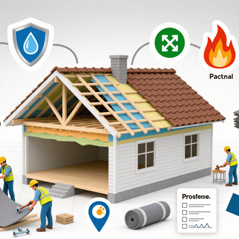
10 Tips for Choosing the Right Insulation Membrane
Set Thermal Targets with R-Values, U-Values, and Climate-Zone Data
Insulation membranes should begin with a thermal target, not a product label. R-value measures resistance to heat flow; higher values generally reduce transmission. U-value measures overall heat transfer; lower values perform better. In simple assemblies, U-value is approximately the inverse of total R-value. Real walls are less tidy. Fasteners, joints, moisture, and compression create thermal bridges.
The International Energy Agency reported in Buildings 2023 that buildings used about 30% of global final energy in 2022. That makes accurate thermal planning practical, not decorative. Use climate-zone data from ASHRAE 169 or local energy codes to set roof, wall, and floor targets. Cold climates often require stronger winter resistance. Hot, humid zones also need careful vapor control and solar-load planning. A high R-value alone cannot prevent condensation.
Tip: Compare whole-assembly U-values, not membrane R-values alone. Ask for tested data at the expected thickness and temperature. The U.S. Department of Energy notes that insulation performance changes with installation quality, density, moisture, and aging. Check these conditions before approving a specification.
Tip: Draw the thermal layer continuously across corners and penetrations. A small gap near a window can undermine an impressive laboratory rating. I have found that site measurements often expose assumptions hidden in design documents. Recheck the target after drainage, ventilation, and fire requirements are included. Thermal performance should remain credible under real construction conditions.

Choosing an insulation membrane starts with moisture, not thickness. The IEA’s Buildings 2023 report states that buildings consume about 30% of global final energy. Poor moisture control can reduce insulation performance and accelerate material damage.
Request ASTM E96/E96M results before comparing products. This test reports water vapor permeance under defined dry-cup or wet-cup conditions. The method matters. A membrane tested with the wet-cup procedure may show different results than one tested dry-cup. Do not compare numbers blindly. Record temperature, relative humidity, and test direction.
Match the result to the assembly’s moisture risk. In many North American codes, Class I vapor retarders measure 0.1 perm or less, Class II measures above 0.1 to 1 perm, and Class III measures above 1 to 10 perms. These limits are useful, but climate, indoor humidity, wall orientation, and drying potential still control the decision. A cold, humid climate may need stronger vapor control on the warm side. A mixed climate may need more drying flexibility. That judgment is easy to oversimplify.
Check every layer. Include sheathing, insulation, cladding, and interior finishes. Seal laps and penetrations with compatible materials. Field workmanship can defeat excellent laboratory data. The U.S. Department of Energy identifies air sealing and insulation as key energy-efficiency measures, yet membranes are not automatically air barriers. I still verify both functions. ASTM E96 measures vapor transmission, not leakage, drainage, or installation quality. That distinction is often missed.
Choosing an insulation membrane starts with three questions: how tightly does it control air, water, and wind? A useful ten-point screen also checks seams, laps, penetrations, drainage, UV exposure, substrate compatibility, installation temperature, repairability, and test documentation.
ASTM E2178 measures air permeance at a specified pressure. Many building codes use 0.02 L/(s·m²) at 75 Pa as an air-barrier benchmark. The U.S. Department of Energy reports that air leakage may represent 25–40% of heating and cooling energy use in typical homes. That figure makes continuity more important than impressive laboratory claims. Inspect every overlap and fastener. Small gaps matter.
ASTM E331 evaluates water penetration under static pressure, commonly using 2.86 kPa for 15 minutes. ASTM E330 examines structural performance under uniform air pressure, helping assess wind resistance and attachment stability. These tests answer different questions. Passing E2178 does not prove water resistance. Passing E331 does not confirm wind durability. On site, wind-driven rain often reaches a poorly detailed corner first. It is easy to overlook. Review pressure ratings, drainage paths, and joint details together. Test results can also be misread when the specimen differs from the installed wall. That deserves more attention. References: U.S. Department of Energy, Energy Saver; ASTM International, E2178, E331, and E330 test standards.
Compare air, water, and wind resistance under ASTM E2178, ASTM E331, and ASTM E330.
The chart compares representative pressure levels used for testing: 75 Pa for ASTM E2178 air permeability, approximately 300 Pa for the commonly referenced 6.24 psf ASTM E331 water test, and 3,000 Pa as an illustrative structural wind-pressure level for ASTM E330. ASTM E330 and ASTM E331 test pressures are project-specific and do not create universal product pass/fail values.
10 Tips for Choosing the Right Insulation Membrane
Evaluate Reflectivity, Emissivity, and Thickness with ASTM C1371 Data
Choosing an insulation membrane requires more than comparing product labels. Start with measured thermal data, especially emissivity results from ASTM C1371. This test uses a portable emissometer to assess how readily a surface releases radiant heat. Lower emissivity can reduce radiant heat transfer when the reflective surface faces an appropriate air space.
Reflectivity deserves careful attention too. ASTM C1371 does not directly measure solar reflectance. Ask for separate reflectance data and confirm the test method, surface condition, and measurement direction. A bright surface may look highly reflective but perform differently after dust, oxidation, or installation damage. Details matter.
Thickness affects handling, compression resistance, and the space available for air gaps. It does not automatically prove better thermal performance. Compare thickness with declared R-value, facing durability, and installation conditions. In field inspections, small gaps around joints often undermine impressive laboratory figures. I have also seen specifications treated as permanent facts, although materials can change with moisture and aging. That assumption needs review. Use current, traceable test reports, and check whether the tested membrane matches the actual construction. A qualified building professional can then assess condensation risk, ventilation, and local requirements before selection.
| No. | Selection Tip | Membrane or Surface Type | Typical Thickness | Typical Solar Reflectance | Typical Hemispherical Emittance | Relevant Test Basis | Practical Interpretation |
|---|---|---|---|---|---|---|---|
| 1 | Prioritize a low-emittance surface when the membrane faces an enclosed air space. | Clean, smooth aluminum foil surface | 0.02–0.10 mm | 0.70–0.85 | 0.03–0.05 | Emittance: ASTM C1371 Solar reflectance: ASTM C1549 or ASTM E903 | A low emittance can reduce radiation across the adjacent air space, provided the surface remains clean and faces the cavity. |
| 2 | Check whether the reflective layer is protected from oxidation, dust, and handling damage. | Protected or laminated foil membrane | 0.10–0.30 mm | 0.65–0.82 | 0.04–0.08 | ASTM C1371 for emittance; visual inspection for surface condition | Protection can help preserve optical performance, but the exposed surface—not a hidden foil layer—controls radiant exchange. |
| 3 | Do not use reflectance as a substitute for thermal resistance. | Metallized polymer film | 0.03–0.20 mm | 0.55–0.80 | 0.20–0.40 | ASTM C1371 for emittance; ASTM C1549 or ASTM E903 for reflectance | A shiny appearance may indicate high reflectance, but a higher emittance than foil can reduce the radiant-barrier effect. |
| 4 | Compare thickness only within products with similar construction and test conditions. | Multilayer reflective membrane with air-bubble or spacer core | 3–10 mm | 0.65–0.85 | 0.05–0.20 | ASTM C1371 for exposed low-emittance surfaces; system thermal testing recommended | Added thickness may create spacing, but the thermal benefit depends strongly on enclosed air layers and installation orientation. |
| 5 | For roof-facing applications, evaluate solar reflectance and temperature exposure separately. | White or light-colored polymer membrane | 0.8–2.0 mm | 0.75–0.90 | 0.80–0.90 | Solar reflectance: ASTM C1549 or ASTM E903; emittance: ASTM C1371 | High reflectance can reduce solar absorption, while high emittance supports long-wave heat release from the surface. |
| 6 | Use a documented ASTM C1371 result rather than judging emissivity from color or gloss. | Dark polymer or bituminous-coated membrane | 1.0–4.0 mm | 0.05–0.30 | 0.85–0.95 | ASTM C1371 for emittance; ASTM C1549 or ASTM E903 for solar reflectance | Dark surfaces commonly absorb more solar radiation, even though their thermal emittance may be high. |
| 7 | Account for seams, fasteners, punctures, and overlaps when selecting the effective membrane thickness. | Reinforced woven-film membrane | 0.20–0.60 mm | 0.40–0.75 | 0.35–0.75 | ASTM C1371 for surface emittance; manufacturer or project testing for assembly performance | Reinforcement improves handling strength, but joints and penetrations can dominate air, moisture, and thermal performance. |
| 8 | Verify that the measured surface is the same surface exposed in the installed assembly. | Foil-faced fibrous or foam-backed membrane | 10–50 mm | 0.65–0.85 | 0.03–0.08 | ASTM C1371 for foil-facing emittance; ASTM C518 or ASTM C177 for thermal resistance of the assembly | The facing may provide a low-emittance surface, while the backing contributes most of the conductive thermal resistance. |
| 9 | Request measurements taken on clean, representative samples and review the test date. | Aged, dusty, or weathered reflective surface | Varies by construction | 0.35–0.75 | 0.10–0.60 | ASTM C1371 measurement should identify sample condition and exposed surface | Dust, oxidation, coatings, and abrasion can increase emittance or reduce reflectance compared with new-sample values. |
| 10 | Choose the membrane according to the complete hygrothermal design, not optical values alone. | Composite vapor-control and radiant membrane | 0.15–2.0 mm | 0.55–0.85 | 0.05–0.35 | ASTM C1371 for emittance; vapor permeance and air-leakage testing as specified for the project | Also verify vapor control, air sealing, water management, fire performance, durability, and compatibility with adjacent materials. |
Choosing the right insulation membrane requires more than comparing thickness and price. Verify its fire classification under EN 13501-1 before reviewing other features. The classification covers reaction to fire, smoke production, and flaming droplets. Look for clear markings such as A1, A2, B, or C, with smoke and droplet ratings included. A label showing only “fire resistant” is not enough.
Request the complete test report, not a cropped certificate. Check whether the test applies to the membrane alone or the full wall, roof, or floor assembly. Substrate type matters. So do thickness, air gaps, adhesives, joints, and protective layers. A membrane tested behind plasterboard may perform differently when left exposed. Installation instructions should match local construction standards and the project’s inspection requirements.
Durability also needs evidence. Review tensile strength, water exposure, temperature limits, and resistance to punctures during handling. On site, inspect overlaps, sealed edges, service penetrations, and damaged sections before covering them. Small gaps can weaken a carefully tested system. I have found that installation teams sometimes follow the product sheet but miss the drawing details. That gap deserves attention. Keep batch records and photographs, even when the work looks routine. Retest assumptions when the building design changes. A reliable choice is supported by documents, realistic site checks, and installers who understand both the rating and its limits.
Contact
KYOCERA SGS Precision Tools, Inc.
(330) 686-5700
150 Marc Drive
Cuyahoga Falls, OH 44223
Products
Resources