
KYOCERA SGS Precision Tools Group
Selecting the right Vacuum Air Flow Meter can determine whether a vacuum system runs smoothly or wastes valuable energy. A reliable meter helps engineers monitor leaks, confirm pump performance, and protect sensitive chambers. The wrong choice can create unstable readings, especially when pressure changes quickly.
John F. O’Hanlon, author of A User’s Guide to Vacuum Technology, has emphasized a practical measurement principle: “A measurement is only useful when its conditions are understood.” That idea matters here. A meter rated for clean laboratory air may perform poorly near oil vapors, dust, moisture, or pulsating flow. Small details matter. Tube position matters. Calibration matters. Even room temperature can influence the displayed value.
This guide presents seven practical tips for choosing a Vacuum Air Flow Meter. It examines measurement range, accuracy, response time, gas compatibility, connection size, calibration records, and maintenance needs. Each point connects the specification sheet with real workshop conditions, where fingerprints, warm tubing, and hurried installation can affect results.
Do not choose by price alone. That is tempting.
A low-cost instrument may look sufficient during a quick test. Later, its limited resolution can hide a small leak or exaggerate flow changes. I have seen specifications appear impressive until the actual operating range was checked carefully. That mistake is easy to repeat. The better approach is deliberate: define the vacuum level, identify the gas, observe the expected flow, and compare those facts with the meter’s documented performance. Reliable selection begins with honest conditions, not optimistic assumptions.
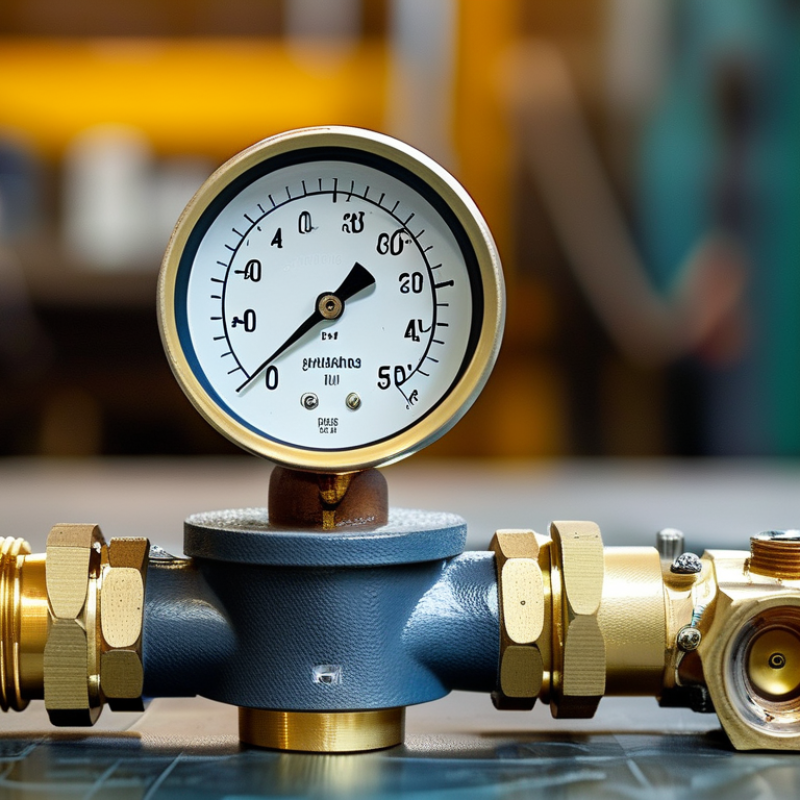
Choosing a vacuum air flow meter starts with understanding the measurement requirement, not the instrument label. Define the gas, pressure range, expected flow, temperature, and reference conditions. Flow shown in sccm is not interchangeable with actual volumetric flow at low pressure. ISO 21360-1 explains standardized methods for measuring vacuum pumping speed, supporting consistent test conditions. Tip 1: State whether you need mass flow or volumetric flow. Tip 2: Record absolute pressure, not gauge pressure. Tip 3: Match the meter’s range to normal operation, rather than its maximum rating.
Installation can change the reading. Keep tubing short, avoid sharp bends, and check for leaks near fittings. The U.S. Department of Energy reports that compressed-air leaks can waste 20–30% of system capacity, although vacuum losses may behave differently. That difference matters. Tip 4: Specify the leak-test method. Tip 5: Confirm gas compatibility and contamination limits. Tip 6: Choose response time based on process changes, not marketing claims. A slow sensor may hide brief flow spikes.
Calibration records support reliable decisions. Ask for accuracy across the working range, temperature effects, and traceability to recognized standards. NIST guidance emphasizes documented uncertainty when measurements support quality decisions. Tip 7: Require calibration data at your actual pressure range. I have seen teams accept a tiny full-scale error as “high accuracy”; that can be misleading at low flow. Recheck the setup after maintenance, because even a clean-looking connector can disturb a sensitive measurement.
| Tip | Measurement Requirement | Relevant Parameters | Recommended Selection Check | Why It Matters |
|---|---|---|---|---|
| 1 | Define the vacuum pressure range | Absolute pressure; operating range in Pa, mbar, Torr, or micron | Select a meter whose specified operating range covers the lowest and highest expected absolute pressures, with additional margin where practical. | Gas-flow behavior and sensor response can change substantially as pressure moves from rough vacuum toward atmospheric pressure. |
| 2 | Match the required flow range | Minimum and maximum flow; sccm, slm, m³/h, or actual volumetric flow | Ensure the normal operating point is comfortably within the calibrated range rather than close to the lower or upper limit. | A range that is too large may reduce useful resolution, while an undersized range can cause overload or inaccurate readings. |
| 3 | Clarify standard versus actual flow | Standard volumetric flow, actual volumetric flow, reference temperature, and reference pressure | Confirm whether the output is reported at a defined standard condition or at the meter's actual inlet conditions. | The same mass flow can produce different volumetric readings when pressure or temperature changes. Standard conditions must be stated for meaningful comparison. |
| 4 | Check gas compatibility | Gas type, density, viscosity, corrosiveness, moisture, and particulate content | Verify calibration gas requirements and wetted-material compatibility. Use a gas correction factor only when it is supplied or validated for the application. | Thermal, pressure-based, and other measurement methods respond differently to gas properties. Reactive or contaminated gases may also damage the sensor. |
| 5 | Evaluate accuracy and repeatability | Accuracy, repeatability, zero stability, calibration interval, and stated uncertainty | Read the complete accuracy specification, including whether it is a percentage of reading, full scale, or a combined error. Check the calibration conditions. | A meter with suitable resolution may still be unsuitable if its total measurement uncertainty is greater than the process tolerance. |
| 6 | Consider response time and pressure drop | Response time, sampling rate, allowable pressure loss, line volume, and flow-path conductance | Choose a response time appropriate to the process and confirm that the meter's pressure drop will not disrupt the vacuum level or pump performance. | Dead volume, restrictions, and long tubing can delay readings and change the pressure-flow conditions being measured. |
| 7 | Plan installation and data integration | Connection size, orientation, temperature limits, ingress protection, analog or digital output, and communication protocol | Confirm the port and seal type, installation orientation, environmental rating, power requirements, output scaling, and compatibility with the control or data-acquisition system. | Correct mechanical installation and signal compatibility help prevent leaks, electrical noise, incorrect scaling, and avoidable commissioning delays. |