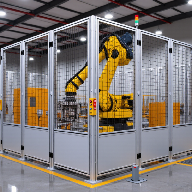
A Robo Safety Fence is more than a metal barrier around an industrial robot. It is a controlled boundary between moving machinery and people. When designed correctly, it combines physical panels, access gates, interlocks, sensors, and emergency stops. Each part has a specific job. Together, they reduce the chance of unexpected contact.
Roberta Nelson Shea, a recognized machinery-safety specialist, explains the guiding principle clearly: “A safeguard is effective only when people can trust it every time.” That trust comes from practical details. A gate should not open while the robot is moving. A broken panel should remain visible. A reset button should sit outside the hazard zone. Small choices matter.
The fence usually works with the robot’s control system. If an interlocked gate opens, the safety circuit sends a stop signal. The robot then enters a safe state before anyone reaches the work area. Some systems also use light curtains, scanners, or pressure-sensitive devices. These tools can improve protection around loading points and maintenance spaces.
Still, no fence is perfect. Human behavior, poor maintenance, and incorrect installation can weaken the entire system. A dusty sensor may fail to detect access. A bypassed gate switch creates a serious gap. That is why risk assessment, inspection, training, and documented testing remain essential. This article explains how a Robo Safety Fence works, what components it uses, and where its limits may appear in real workplaces. Safety is never finished.
What Is a Robo Safety Fence and How Does It Work?
A robo safety fence is a physical barrier around an industrial robot and its operating area. It separates people from moving arms, tools, payloads, and unexpected motion. The fence usually includes guarded panels, controlled access gates, and a safety-rated stopping function. When someone opens a gate, the robot should stop before the person reaches a hazardous movement.
ISO 10218-1 focuses on the safety requirements for industrial robots, including protective measures, stopping functions, operating modes, and safe control behavior. A fence alone does not satisfy these requirements. The complete installation needs a documented risk assessment, suitable safety distances, and validated protective devices. Gate interlocks must prevent automatic operation while access remains open. Emergency stops should be easy to reach and clearly identified.
The details matter.
In practice, an assessor should check reach-through gaps, gate alignment, restart controls, and stopping time. A robot may stop safely at one speed but require more distance at another. The surrounding equipment can also create blind spots or trapping points. ISO 10218-1 should be applied with the relevant edition and with system-level requirements, such as those addressed by ISO 10218-2. A checklist helps, but it is not enough. Even a carefully designed fence can fail if workers bypass it during setup or maintenance. Regular training, inspection, and documented validation remain essential.
A robo safety fence separates people from hazardous robot motion, but it is more than a metal barrier. It usually combines fixed guarding, access doors, interlocks, and presence-sensing devices. For example, a light curtain can detect a hand entering the cell. A safety scanner may monitor the floor near loading points. The exact device depends on reach distances, robot speed, tooling, and workplace layout.
Detection must trigger a protective stop before a person reaches the danger zone. The control system removes motion energy and prevents an automatic restart. A stopped robot is not automatically safe. Gravity, stored pressure, sharp tooling, or a suspended load may still create hazards. Operators should verify the stop distance through testing, not assumptions. Small gaps can matter. Dust, reflections, or poor sensor alignment can also reduce detection reliability.
ISO/TS 15066 provides biomechanical guidance for collaborative robot applications. Its force, pressure, and energy values vary by body region and contact type. A brief touch differs from a crushing impact. These values support risk assessment; they do not replace guarding or authorize every operating condition. Engineers should consider speed, payload, tool shape, stopping time, and foreseeable misuse. In practice, teams can misjudge human behavior. A worker may reach around a fence or enter during maintenance. Clear procedures, lockout controls, validation records, and regular inspections remain essential. Safety design is never perfect. That is why it needs review.
A robo safety fence separates people from moving robots, tools, and stored mechanical energy. Its value depends on risk assessment, not fence height alone. ISO 12100 requires designers to define machine limits, identify hazards, estimate risk, and reduce it through protective measures.
A practical review checks reach-through gaps, access routes, robot stopping distance, and unexpected restart conditions. A 1.2-meter fence may look substantial, yet an exposed transfer opening can defeat the entire layout.
OSHA safeguarding rules require protection from points of operation, rotating parts, and other dangerous machine areas. The layout should place gates outside normal robot reach whenever possible. Interlocked gates should stop hazardous motion before a person can enter.
Lockout procedures must also address pneumatic pressure, gravity, electrical power, and stored energy.
That figure covers all industries, but it reinforces why “the robot usually stops” is not a reliable safeguard.
Walk the cell before approving the drawing. Watch a real operator load a part, clear a jam, and clean the floor. Small habits reveal large risks.
A frequent weakness is treating the fence as the safety system. It is only one layer. ISO 12100 favors inherently safer design before relying on guards and procedures.
Some layouts still need redesign after testing.
That is not failure; it is evidence that the assessment is working.
Sources: ISO 12100:2010; OSHA 29 CFR 1910.212 and 1910.147; U.S. Bureau of Labor Statistics, Census of Fatal Occupational Injuries, 2023.
A robo safety fence separates people from moving equipment, but its protection depends on regular validation. Begin with a documented risk assessment. Check every panel, post, bracket, and anchor for movement, corrosion, or sharp damage. Even a small gap can create an unsafe reach-through point.
Test each access door and interlock under controlled conditions. Opening a protected door should prevent hazardous motion or initiate a safe stop. Confirm that the system cannot restart unexpectedly after the door closes. Test emergency stops, reset controls, presence sensors, and warning indicators according to the approved procedure. Record the result, date, tester, and any corrective action.
Maintenance should match operating conditions. High vibration, dust, frequent access, and heavy cleaning may require shorter inspection intervals. Walk around the entire fence, not only the visible front section. Look for loose fasteners, bent mesh, damaged hinges, and objects stored against the barrier. Remove unauthorized changes immediately.
A checklist helps. It is not enough. A rushed inspection may miss a worn hinge or a defeated interlock. One weakness can change the whole protection system. If a test fails, isolate the equipment and prevent use until a qualified person verifies the repair. Recheck the affected function after maintenance, because repairs can introduce new alignment or reset problems. Safety records should remain clear, dated, and available for review.
| Validation and Maintenance Area | Purpose | Test or Inspection Method | Acceptance Criteria | Recommended Timing | Required Record |
|---|---|---|---|---|---|
| Fence Panel and Post Condition | Confirm that the physical barrier remains capable of preventing unintended access to the robot hazard zone. | Visually inspect panels, posts, brackets, welds, fasteners, and protective coatings. Check for bending, cracks, corrosion, sharp edges, and missing hardware. | No loose, damaged, corroded, or sharp components; panels remain securely supported and cannot be displaced by normal operating forces. | Before each shift and after any impact, modification, or abnormal event. | Inspection date, inspector, findings, corrective action, and close-out date. |
| Guard Opening and Reach-Through Protection | Prevent a person from reaching the robot or other hazardous moving parts through, over, under, or around the fence. | Measure openings and distances from the fence to hazardous motion. Evaluate reach paths using the applicable safety-distance and reach-distance criteria. | Openings and separation distances comply with the risk assessment and applicable machinery-safety requirements; no accessible hazard remains during normal operation. | During commissioning and whenever the fence, robot layout, tooling, or hazard position changes. | Measured dimensions, risk-assessment reference, test equipment, and approval signature. |
| Access Door Alignment and Mechanical Condition | Ensure that doors close fully and cannot be easily defeated, bypassed, or left partially open. | Open and close each door repeatedly. Check hinges, latches, stops, handles, alignment, sagging, and clearance. Apply the normal operating force to verify stability. | Door closes completely, latches correctly, does not bind, and cannot be opened unintentionally from the protected side. | Weekly and after maintenance, impact, or door adjustment. | Door identification, inspection result, defects, and repair details. |
| Interlock Device Function | Ensure that opening a guarded access point initiates the required safety response. | With the robot operating in a controlled test condition, open each access door and verify that the safety-related stop function is initiated. Attempt restart while the door is open. | Hazardous motion stops as defined by the risk assessment, and automatic or normal restart is prevented while the door is open. | At commissioning, before each shift where required by the risk assessment, and after interlock maintenance. | Door number, stop response, restart test result, and person performing the test. |
| Emergency Stop Function | Verify that emergency-stop devices provide a readily accessible means of stopping hazardous motion. | Activate each emergency-stop device during a controlled test. Confirm that motion stops and that the device remains actuated until manually reset. | The required stop category and response are achieved; reset does not by itself restart the robot; all emergency-stop devices are clearly identified and accessible. | Before operation and after electrical or control-system work. | Device location, activation result, reset result, and corrective actions. |
| Safety-Control Circuit Monitoring | Detect faults in interlocks, emergency stops, wiring, or safety-related control components before the machine can operate unsafely. | Use the approved diagnostic or validation procedure to test input channels, output channels, reset logic, and fault detection. Do not introduce faults unless the procedure is authorized and controlled. | The safety function responds to the defined single faults and produces the required diagnostic or safe-state response. | During initial validation, after control-system changes, and at the interval specified by the safety system assessment. | Safety-function identifier, test procedure, results, faults detected, and validation approval. |
| Robot Stopping Performance | Confirm that the robot stops within the time and distance used to establish the protective separation distance. | Measure stopping time and, where applicable, stopping distance under representative payload, speed, program, and tool conditions. Use calibrated measurement equipment and the approved test method. | Measured stopping performance does not exceed the values used in the risk assessment and safety-distance calculation. | At commissioning, after changes to speed, payload, software, tooling, or safety controls, and at the interval defined by the risk assessment. | Operating conditions, measured time or distance, instrument details, and comparison with design values. |
| Fence Stability and Anchorage | Ensure that the enclosure remains fixed and maintains the required protective position during operation. | Inspect floor anchors, base plates, joining brackets, fasteners, and post plumbness. Check for movement, vibration damage, and interference with nearby equipment. | Anchors and fasteners are secure, posts remain stable, and the fence has no movement that could create an access gap or reduce protection. | Monthly and after relocation, impact, construction work, or significant vibration. | Anchor inspection results, torque or condition checks where specified, and repair records. |
| Safety Signage and Access Identification | Communicate the presence of hazards, restricted access, and required operating controls. | Check warning signs, restricted-entry labels, emergency-stop labels, and access-point identification for visibility, legibility, and correct placement. | Signs are visible from relevant approach points, readable, securely attached, and consistent with the current hazard and operating procedure. | Monthly and whenever the cell layout or hazard information changes. | Signage checklist, location, condition, and replacement date if applicable. |
| Housekeeping and Clearances | Prevent stored materials, debris, cables, or tools from creating bypass routes or obstructing safe access. | Inspect the perimeter, door swing area, emergency-stop access, floor condition, and space around the robot cell. Remove unauthorized objects. | No material blocks access, interferes with door operation, creates a climb-over route, or obstructs emergency controls. | Before each shift and during routine operator inspections. | Operator checklist and records of repeated housekeeping issues. |
| Change-Control Review | Ensure that modifications do not reduce the effectiveness of the safeguarding system. | Review changes to robot programs, tooling, production speed, fence layout, access points, safety circuits, and nearby equipment. Repeat affected validation tests. | The risk assessment, safety-distance calculation, drawings, procedures, and validation records are updated before release to production. | Whenever a change may affect the hazard, safeguarding, stopping performance, or safety-related control system. | Change request, revised documents, test results, authorization, and implementation date. |
| Periodic Functional Audit | Confirm that the complete safeguarded cell continues to perform as intended over its service life. | Perform a documented review of fence integrity, access controls, emergency stops, stopping performance, signage, maintenance history, and outstanding corrective actions. | All required safety functions pass testing, deficiencies are corrected or formally controlled, and records remain traceable. | At the interval established by the risk assessment and site procedures; review at least after significant incidents or modifications. | Signed audit report, open-action list, completion evidence, and next review date. |

Contact
KYOCERA SGS Precision Tools, Inc.
(330) 686-5700
150 Marc Drive
Cuyahoga Falls, OH 44223
Products
Resources