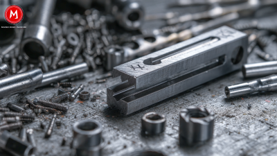
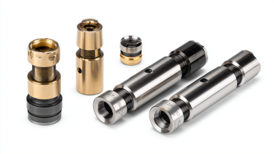
Choosing a milling machine is not about buying the largest spindle or the most impressive control. It is about matching the machine to the material, cutter, workpiece, and production volume. A small workshop cutting aluminum brackets has different needs from a shop machining steel plates all day. “Choose for the cut you actually make, not the machine you hope to need,” says milling applications specialist Elena Park. That practical rule frames this guide. A note: spindle speed alone never tells the whole story.
The sections ahead compare vertical and horizontal mills, manual and CNC controls, work envelopes, spindle power, and tooling. Each choice affects the cut. A rigid frame helps reduce chatter; suitable spindle speed and feed rates protect the cutter and surface finish. Check the table dimensions against your largest part, then consider how you will clamp it. A vise, fixture plate, or rotary table can change what the machine can handle. Measure twice.
We will also look at materials, accuracy, maintenance, and budget, including the costs of tooling and setup. For cutting milling operations, the best machine is the one that produces repeatable results within your actual requirements. Be honest about those requirements. Buyers sometimes focus on a future job that may never arrive, while overlooking today’s bottleneck. That is worth reconsidering. Use the guide to compare options, ask suppliers specific questions, and verify capacity with real part dimensions before making a decision.
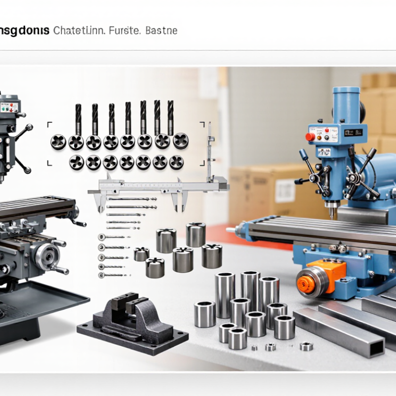
Before choosing a milling machine, list the cuts you will actually make. A job involving broad face milling differs from one requiring narrow slots, drilled holes, or contoured surfaces. Note the workpiece material, its size, and how often the machine will run. Cutting aluminum in short batches places different demands on the setup than removing material from a large steel block. Small details matter.
Define accuracy in measurable terms. A drawing might call for a slot width within 0.05 millimeters, while another part only needs a clean, consistent fit. Check the required tolerances, surface finish, and repeatability before comparing machine specifications. Also consider how you will verify results: a micrometer can check thickness, while a dial indicator can reveal movement or alignment errors. A machine’s stated precision cannot compensate for a poorly secured workpiece or worn cutting tool.
Think about the complete setup, not just the machine. Tool reach, spindle rigidity, table travel, and available fixturing all affect the cut. If parts are long, confirm there is enough travel and support. In practice, I have seen a tight tolerance assumed to require a more complex machine, when a better fixture and careful measurement addressed the real problem. I still check that assumption. Describe one representative job, including its material, dimensions, and tolerance, before settling on a machine.
Choosing a milling machine starts with the workpiece material, not just its size. Aluminum cuts readily, but it can cling to a dull tool and leave a smeared finish. A machine with adjustable spindle speed and reliable chip removal helps manage heat and buildup. For stainless steel, prioritize rigidity and steady feed control. Excessive vibration can quickly wear the cutter or mark the surface. Cast iron is abrasive, so a stable setup and suitable tooling matter more than maximum spindle speed. Plastics need sharp cutters and careful heat control; too much friction can soften an edge before the cut is complete.
Tips: Check the material’s hardness, thickness, and shape before choosing. Test the setup on a small offcut when possible. Watch the chips: color, shape, and heat can reveal problems early.
Material alone does not determine the best machine. Cutter geometry, workholding, and the required finish also affect the choice. A rigid machine may suit difficult alloys, while lighter work can often be handled by a less powerful unit. It is easy to overestimate power and overlook vibration or chip clearance. That judgment deserves a second look.
Match the machine type to the workpiece material
Relative suitability is rated from 1 (less suitable) to 5 (well suited). These general ratings are a selection guide, not a substitute for checking machine rigidity, spindle power, tooling, workholding, and cutting parameters for the specific job.
A milling machine’s table size is not the same as its usable travel. Measure the workpiece, fixture, clamps, and tool approach space together. For a 600 mm-long part, a 750 mm X-axis travel may provide a practical allowance, but the setup can change that figure. Check Y and Z travel too; a tall vise or long cutter can consume Z clearance quickly. Leave room for tool changes and chip evacuation. Small details matter.
Compare the total setup weight with the machine’s rated table load, then check spindle power and torque at the speeds your cutter needs. Peak power alone can mislead: a machine may not sustain it during heavy cuts. ISO 230-1:2012 describes geometric accuracy tests for machine tools, while ISO 10791-2:2001 covers accuracy testing for machining centers. These standards help assess positioning and geometry, not cutting capacity under every load. That distinction is easy to miss. A machine that passes an accuracy check may still struggle with a heavy steel cut. Record your largest expected workpiece and heaviest fixture, then verify travel, load, and cutting data with the manufacturer’s technical specifications. A checklist helps, but it cannot replace a real setup review.
Choosing a milling machine starts with the material and cut, not the largest number on a specification sheet. Spindle power helps maintain cutting force under load, especially when removing material from steel or using a larger cutter. For light aluminum work, excess power may add cost without improving results. Watch for chatter: a spindle that slows or vibrates during a cut can leave rough surfaces and shorten tool life.
Speed matters just as much. Small-diameter tools generally need higher revolutions per minute than large cutters, while tough materials often call for more conservative settings. Check the machine’s speed range and whether it can hold a steady rate under load. It is easy to focus on maximum RPM. That can be misleading.
Tips: Match the collet or holder to your tool shank, and confirm that common cutter sizes are supported. Keep a few spare inserts nearby; a dull edge can disguise itself as a machine problem.
Tooling options affect flexibility and setup time. A machine that accepts several holder types can handle face mills, end mills, and drills with fewer compromises. Consider how easily tools can be changed and whether the workpiece can be clamped securely. Before buying, compare the machine’s power curve, usable speed range, and tooling compatibility against the cuts you make most often. One detail is easy to miss: the stated power may not be available across the full speed range.
| Machine Type | Typical Spindle Power | Typical Spindle Speed | Common Tooling Options | Best Suited For | Key Selection Consideration |
|---|---|---|---|---|---|
| Manual vertical knee mill | About 1–5 hp (0.75–3.7 kW) | About 60–4,200 rpm, depending on pulley or variable-speed design | R8 or ISO 30 spindle tooling; collets, end-mill holders, drill chucks, and face-mill arbors | Repair work, toolrooms, prototypes, and occasional cutting of small or medium parts | Choose for low setup cost and hands-on flexibility. It is less suitable for unattended production or repeatable complex parts. |
| CNC vertical machining center (VMC) | About 10–40 hp (7.5–30 kW) | About 6,000–15,000 rpm; high-speed configurations may reach 20,000 rpm or more | ISO 30, ISO 40, or HSK tool interfaces; automatic tool changer with end mills, drills, taps, and face mills | General-purpose production, prismatic parts, pockets, drilled features, and multi-operation jobs | Match power and torque to the material and cutter size. Higher maximum rpm benefits small tools and aluminum, while lower-speed torque supports heavier cuts. |
| CNC horizontal machining center (HMC) | About 15–50 hp (11–37 kW) | About 4,000–12,000 rpm; some models offer higher-speed spindles | Commonly ISO 40 or ISO 50; automatic tool changers, face-mill arbors, boring tools, drills, and indexable cutters | High-volume production, larger prismatic components, and parts requiring machining on multiple sides | Horizontal orientation helps chips fall away from the cutting area and can support multiple-face machining. Check pallet capacity and tool-change requirements. |
| Bed or universal milling machine | About 5–20 hp (3.7–15 kW) | About 50–3,000 rpm, varying with gearbox and spindle configuration | ISO 40 or ISO 50 tooling; arbor-mounted cutters, end mills, face mills, and angle heads on suitable configurations | Long or heavy workpieces, maintenance shops, and cutting that benefits from a rigid table and straightforward setups | Prioritize table size, travel, and rigidity for large work. Confirm that the spindle and available tooling match the cutter diameter and cutting load. |
| Gantry or bridge-type milling machine | About 20–100+ hp (15–75+ kW), depending on machine size and spindle head | About 1,000–12,000 rpm; heavy-cutting configurations may use lower speeds | Typically ISO 40 or ISO 50; large face mills, long-reach cutters, and optional interchangeable or angled heads | Large plates, molds, dies, structural components, and workpieces too large for conventional machine enclosures | Machine structure, work envelope, and head configuration matter as much as spindle power. Verify that the machine can reach all required surfaces without excessive tool overhang. |
Note: Figures are typical ranges for common machine configurations, not guaranteed specifications. Actual spindle power, speed, tool interface, and cutting capacity vary by model, spindle design, and operating conditions. Select tooling compatible with the machine’s spindle interface and the material being cut.
When choosing a milling machine, test its controls with the kind of work you actually do. Can operators set feed, spindle speed, and tool offsets without hunting through menus? Clear displays and repeatable settings matter when a job changes mid-shift. Deloitte’s 2024 Smart Manufacturing Survey found that 92% of manufacturers see smart manufacturing as a competitiveness driver. That is a broad industry finding, not proof that a connected control pays off for every shop. Keep it practical. Check whether the interface supports your operators’ experience and whether training is included.
Inspect the guarding, door interlocks, emergency stop, and chip enclosure in person. A safe machine should let an operator reach routine service points without leaning past sharp chips or hot coolant. Then estimate the full running cost: cutters, inserts, coolant, filters, electricity, maintenance, and downtime. The U.S. Department of Energy’s motor-system guidance estimates that motor-driven systems use about 54% of U.S. manufacturing electricity; this is a sector-wide figure, not a mill-specific forecast. Ask for expected power draw under your typical cutting load. I would not trust a single headline price. Small recurring costs can surprise you. Compare service intervals and replacement-part availability, too. A cheaper machine may become expensive if a routine repair leaves it idle for days.
Contact
KYOCERA SGS Precision Tools, Inc.
(330) 686-5700
150 Marc Drive
Cuyahoga Falls, OH 44223
Products
Resources