How to Choose the Best Multi Hole Drilling Machine
Choosing the best Multi Hole Drilling Machine begins with the workpiece, not the machine’s advertised hole count. List the materials, thicknesses, hole diameters, spacing, and daily production target. A cabinet shop drilling repeated shelf-pin rows has different needs from a metal workshop making precise bolt patterns. Bring a sample part or drawing when comparing machines. Ask suppliers to demonstrate the actual operation, including setup and tool changes. Watch how easily the operator aligns the workpiece and checks hole spacing. Small setup delays can add up across a production run.
Capacity matters, but so do spindle layout, feed control, guarding, and service access. Check whether the machine accepts the bits and fixtures your jobs require. Ask about repeatability, maintenance intervals, available training, and replacement-part lead times. Daniel Mercer, a fictional machine-tool specialist used here for illustration, offers this original, unsourced line: “A good drilling machine earns its place through repeatable holes and simple, reliable setup.” Treat that as a decision principle, not a verified quotation. Compare total operating costs as well as purchase price. If possible, test the machine on your material and inspect several finished parts. Measure the holes. Check their positions. A few details can reveal limitations that a brochure will not. No single model suits every shop; the best choice is the one that meets your real tolerances, workload, and operator needs consistently.
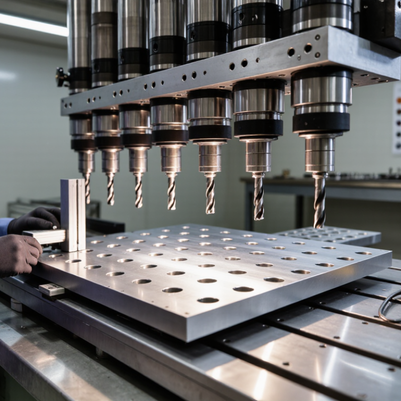
Identify the Workpieces and Hole Requirements
Identify the workpiece before comparing machine layouts. Record its material, length, width, thickness, surface condition, and how firmly it can be clamped. A thin panel may flex under pressure; a cast or laminated part may vary between batches. Check a real sample, not only the drawing. Small differences matter.
Next, define every hole: diameter, depth, spacing, edge distance, and whether it is blind or through. Specify positional tolerance and acceptable burrs, too.
The International Federation of Robotics’ World Robotics 2024 report counted about 4.28 million industrial robots operating worldwide in 2023. That figure shows the scale of automated production, but it does not prove automation suits every drilling job.
Match the machine’s spindle arrangement and fixture to the actual hole pattern. Test a representative workpiece and measure several holes after clamping and release. Measure twice.
I have seen a layout look perfect on paper, then shift when a narrow part was secured; that is a useful warning, not a universal rule. Keep the test results, including setup time and rework, before settling on a configuration.
Compare Machine Types and Spindle Configurations
Multi-hole drilling machines differ in how they position work and drive their tools. A fixed-head machine suits repeat parts with the same hole pattern; setup is quick once the jig is aligned. An adjustable-head model offers more flexibility when spacing changes, but each adjustment adds time and another chance for misalignment. CNC models can store patterns and coordinate movement, though they may be unnecessary for short runs. Simple is sometimes better.
Spindle layout matters as much as machine type. Inline spindles work well for rows of holes, while a grouped pattern can match panels with clustered holes. Check spindle pitch against the part drawing, not just the machine’s stated capacity. A shared drive keeps spindles synchronized; independent drives offer more speed control but can increase maintenance needs. Also confirm chuck size, rotation direction, and bit compatibility. Easy to overlook. Before choosing, test the actual material with a sample setup and inspect hole edges, depth, and chip removal. A clean result in thin stock may not predict performance in denser material. The right configuration depends on tolerances, batch size, floor space, and how often the pattern changes.
Evaluate Drilling Capacity, Accuracy, and Speed
A multi-hole drilling machine should match the largest workpiece, hole diameter, and material you actually process—not just the maximum figures on its specification sheet. For a 10 mm drill in material requiring a cutting speed of 30 m/min, the standard speed formula gives about 955 rpm: spindle speed equals 1,000 times cutting speed, divided by pi times drill diameter. Machinery’s Handbook presents this relationship as a core machining calculation. Check that the machine can sustain the required speed and feed under load. A fast spindle alone proves little.
Accuracy needs a repeatable test. ISO 230-2:2014 describes how to assess positioning accuracy and repeatability in numerically controlled machine tools; use its measurement principles when comparing axis performance. On your actual material, drill several holes across the work area, then measure their positions and diameters. Look for drift, burrs, and uneven chip removal. One trial is not enough. Tool wear and clamping can change results, and those details are easy to overlook.
Tips: Ask for a timed cycle test using your workpiece and drill size. Record holes per cycle, setup time, and measured variation. Treat advertised speed as a starting point, not a guarantee.
How to Choose the Best Multi Hole Drilling Machine - Evaluate Drilling Capacity, Accuracy, and Speed
Representative specifications for common machine configurations. Actual capacity and accuracy vary with material, tooling, workholding, and machine setup.
| Machine configuration | Typical spindle count | Typical drilling capacity per spindle* | Typical spindle speed | Typical positioning accuracy | Best suited for |
| Compact fixed-head machine | 2–4 | Up to about 10 mm in mild steel | Approximately 500–3,000 rpm | About ±0.10–0.20 mm | Small parts and repeated hole patterns |
| Production multi-spindle drill | 4–8 | About 10–16 mm in mild steel | Approximately 300–2,000 rpm | About ±0.10–0.20 mm | Medium-volume production with a fixed hole layout |
| Adjustable-head drilling machine | 2–6 | About 6–13 mm in mild steel | Approximately 400–2,500 rpm | About ±0.15–0.30 mm after setup | Multiple part designs requiring changeable spindle spacing |
| CNC multi-spindle drilling machine | Typically 2–6 | About 6–16 mm in mild steel, depending on spindle and tooling | Approximately 500–3,000 rpm | About ±0.05–0.10 mm | Repeatable hole patterns, frequent program changes, and closer positioning requirements |
*Capacity figures are indicative for mild steel. Confirm the manufacturer’s rated capacity for the intended material, hole depth, drill type, and number of spindles operating at once. Check repeatability separately from positioning accuracy.
Review Safety Features, Maintenance, and Operating Costs
A multi hole drilling machine should protect the operator during setup and production. Check that guards cover moving parts and that emergency stops are easy to reach from the normal working position. Interlocks should prevent operation when access panels are open. Small details matter. Before comparing models, consider how operators load panels, clear chips, and change tools; each task creates a different exposure. Follow the machine’s operating instructions, and make sure controls are clear and reachable.
Maintenance affects both accuracy and downtime. Ask what routine checks involve: spindle lubrication, belt tension, filter cleaning, and inspection of drill bits. Look for accessible service points and clear maintenance schedules. If a technician must remove several covers for a simple check, that labor can become a recurring expense. Keep a record of tool changes and alignment issues. It may not be perfectly complete at first, but even basic notes can reveal repeated wear.
Operating costs include more than the purchase price. Estimate electricity, compressed air, replacement tooling, planned service, and the cost of production stops. A machine with more drilling heads may shorten cycle time, yet it can also require more tools and maintenance. That adds up. Compare costs using your actual daily workload, not an optimistic target; workloads change, and estimates are sometimes wrong. A practical choice balances safe access, maintainable design, and realistic production needs.
Match Machine Specifications to Production Needs
A multi hole drilling machine should fit the work you actually run, not just the largest job on your schedule. Start with the part’s material, thickness, and hole pattern. A cabinet panel with six evenly spaced holes needs different tooling and setup than a steel plate with varied hole diameters. Check spindle count, spacing range, motor capacity, and maximum workpiece size against real production samples.
Then compare those specifications with your daily output. Estimate how many parts must be drilled per shift, including loading, clamping, tool changes, and inspection. A machine with more spindles may shorten cycle time, but only if its layout matches the hole pattern. Otherwise, operators may need extra passes, reducing the expected gain. Small details matter: can the fence be adjusted quickly, and does the table support long panels without sagging?
Consider material changes and future orders, too. Variable-speed control and adaptable fixtures can help when production includes different materials or hole layouts. Ask for a trial using your own parts, and record cycle time, hole position, and rework. A spec sheet cannot show every setup issue. There is rarely a perfect match; sometimes a simpler machine is easier to keep productive. Recheck your assumptions before buying.

